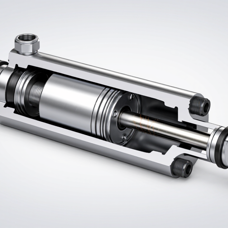
Hydraulic Ram Components turn pressurized fluid into controlled linear force. A typical hydraulic ram, or cylinder, contains a barrel, piston, rod, seals, end caps, and ports. Each part has a specific job. The barrel holds pressure; the piston separates working chambers; the rod transfers force to a load. Small details matter. A worn seal can cause drift. A scored rod can damage seals and invite leakage.
The National Fluid Power Association’s annual industry statistics report tracks fluid-power shipments and market activity, giving manufacturers and buyers context for equipment demand. Technical standards add another layer: ISO 6020-2 specifies mounting dimensions for selected hydraulic cylinders, while ISO 10100 covers cylinder acceptance tests. These sources help frame component selection, but they do not replace checking pressure, stroke, load, speed, and operating conditions for a particular machine. One detail is often overlooked: contamination control affects component life, even when the cylinder looks sound.
Dr. Monika Ivantysynova is a recognized fluid-power researcher whose work examines system efficiency and hydraulic transmission design. A concise takeaway consistent with that engineering perspective is: “A cylinder’s performance depends on the system around it.” This is a paraphrase, not a verified verbatim quotation. It points to a practical truth: pumps, valves, fluid, seals, and mounting all influence ram behavior. The components may look simple. Their interactions are not. This guide explains what each part does, what can wear, and what to inspect before choosing a replacement.
What Are Hydraulic Ram Components?
A hydraulic ram pump uses flowing water, not fuel or electricity, to lift a smaller volume uphill. Its main components are simple: a drive pipe, waste valve, delivery valve, air chamber, and delivery pipe. The source tank must sit above the pump, creating the supply head. The drive pipe carries water toward the waste valve. Its length and diameter strongly affect the pumping cycle.
Here is the water-pumping cycle. Water accelerates through the open waste valve. The valve then snaps shut.
Briefly.
This sudden stop creates water hammer, a pressure surge that opens the delivery valve. Pressurized water enters the air chamber, compressing trapped air before moving into the delivery pipe. As pressure falls, the delivery valve closes. The waste valve reopens, and the cycle repeats many times per minute. The air chamber smooths the pulses, although poorly charged air can reduce performance.
The Development Technology Unit at the University of Warwick describes output using the relationship Qd/Qs ≈ ηh/H.
Here, h is supply head, H is delivery head, and η is efficiency. Practical guidance commonly places efficiency near 60–80%, though field results vary. With a 2-meter supply head, a 10-meter lift, and 70% efficiency, delivered flow may reach about 14% of source flow.
Practical Action’s hydraulic ram guidance also notes that most water passes through the waste valve. The first design estimate is often too optimistic. Pipe friction, valve wear, air loss, and seasonal flow changes matter. A quiet test run does not always mean a reliable installation.